Demand for Economical Machines is increasing due to rising Global energy prices. LETIPTOP recognizes that customers are becoming more aware of their social responsibility. Customers require eco-friendly manufacturing that is both beneficial to the environment and their profit margins. With this in mind, LETIPTOP has used its 15+ years’experience in press brake manufacturing to present to you; the new generation Hybrid Press Brake series. We will let you know how to buy Hybrid Press Brake from both energy saving and configuration.
| Energy Saving: ●Energy Consumption: ●95% less while idle between bends. ●50% less during free fall. ●At least 50% saving when bending. ●If delay time at end of bend is composed, then it is 84% less. ●70% less consumption during return of the upper beam. ●Hydraulic oil tank capacity 60% less |
 |
| E.g. 100T Press Brake | Conventional CNC System | Hybrid System |
| Energy Saving | 0% | Up till 55% |
| Oil Volume | 200L | 2 x 40L |
| Positioning Accuracy | >0.01mm | >0.005mm |
| Noise | 87.6db | 63db |
Configuration:
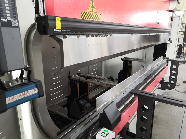
Hybrid Press Brake is mainly composed of frame, sliding block, crowning table, light curtain, Bending Angle Laser Detection Device, Bending Mould & Clamping, Front Support & Backgauge, hydraulic system and CNC control system.
1. Machine Frame
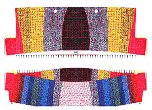
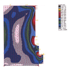
It consists of left and right columns, oil tanks, working table, crowning cylinders (when cylinder crowning system is used), etc.. When bending the plate sheet, the slider and the working table will inevitably produce deformation, so that the bending angle of the workpiece is small at both ends and large in the middle. The function of the crowning system is to compensate the working deflection of the working table, to make the working table produce pre-deformation to track the deflection deformation of the slider, and to control the angle change of the workpiece in the bending length within the tolerance range. We can make the machine with hydraulic crowning or mechanical crowning.

2.Sliding Block
It is mainly composed of sliding block, main oil cylinder, grating ruler, rectangular guide rail and so on. The left and right cylinders are fastened to the frame with bolts, and the piston rod and the slider are connected with spherical blocks and screws. The structure can make the slider to improve the working state of the piston rod under partial load and combination of the piston rod and the slider. The slide block is connected with the frame by a rectangular guide rail. The guide rail is self-lubricating type, only need a few drops of oil every week. A grating ruler is installed on the C-shaped plate on both sides of the frame to control the upper limit positions, lower limit positions, empty stroke and the working stroke, as well as to detect and feedback the synchronous motion of the two piston rods.
Slider Synchronization Control:
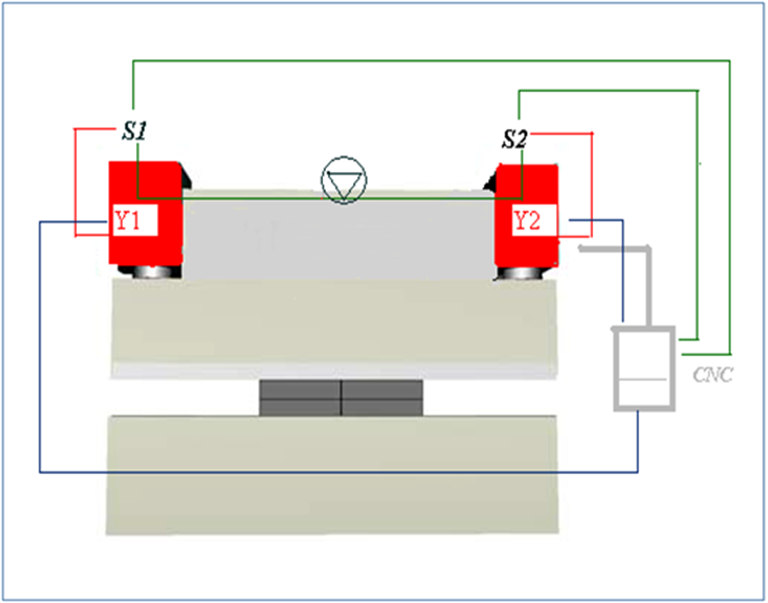
It is electro-hydraulic synchronization technology. Y1 and Y2 axis are the independent motion parameters of two oil cylinders controlled by the CNC system. Two grating rulers are installed C-shaped plate on both sides of the machine frame, which are used to measure the exact distance between the sliding block and the worktable. The grating ruler is connected to the working table through a small frame (C-shaped frame), which eliminates the influence of column deformation on the position of the slider. When the slider is moving, the position data is immediately feed back to the CNC system, and it can measure and output servo valve control signals S1~S2, control the output flow of the two electro-hydraulic servo valves, and synchronize the two cylinders. This position measurement process is closed-loop control.
Accuracy:
●Grating Ruler Accuracy: 0.005 mm
●Slider Repeatability Accuracy Y1, Y2: ±0.01 mm
●Slider Positioning Accuracy Y1, Y2 ± 0.01mm
●Slider Parallel Accuracy Y1, Y2 ± 0.01mm
●Angle Tolerance: ±40’/4 meters full length (2mm thickness cold rolled plate bending
3. Crowning Table:
The deflection compensation system (crowning system) can ensure that the working table and the upper sliding block always remain parallel during the bending operation.
Data such as sheet thickness, length, lower knife opening and tensile strength are input into the CNC controller system, and the bending strength and the offset of the corresponding worktable and upper slider are automatically calculated, and each bending operation will pass the CNC controller system to adjust the protruding amount of the working table automatically to reach the best position. The system provides automatic correction and automatic compensation capabilities. It can conveniently, reliably and accurately adjust the deflection curve of the working table in the full length range to match the deformation curve so that the full length angle is consistent.
 |
 |
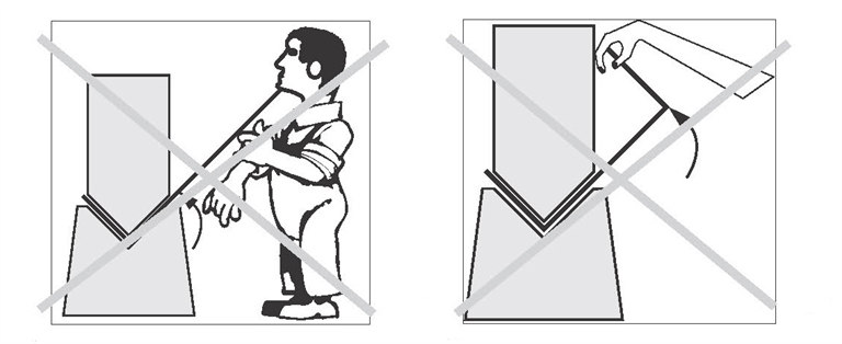
4. Light Curtain:
The Light Curtain is an electrosensitive protective device. It is characterized by the fact that a hazardous motion becomes interrupted or prevented if the light beams produced between the transmitter and receiver unit are interrupted. So it can ensure the safety of workers.
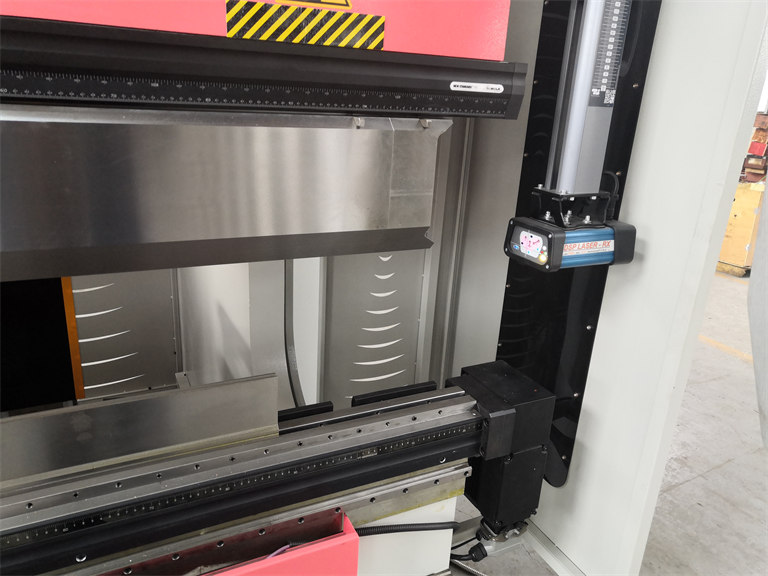
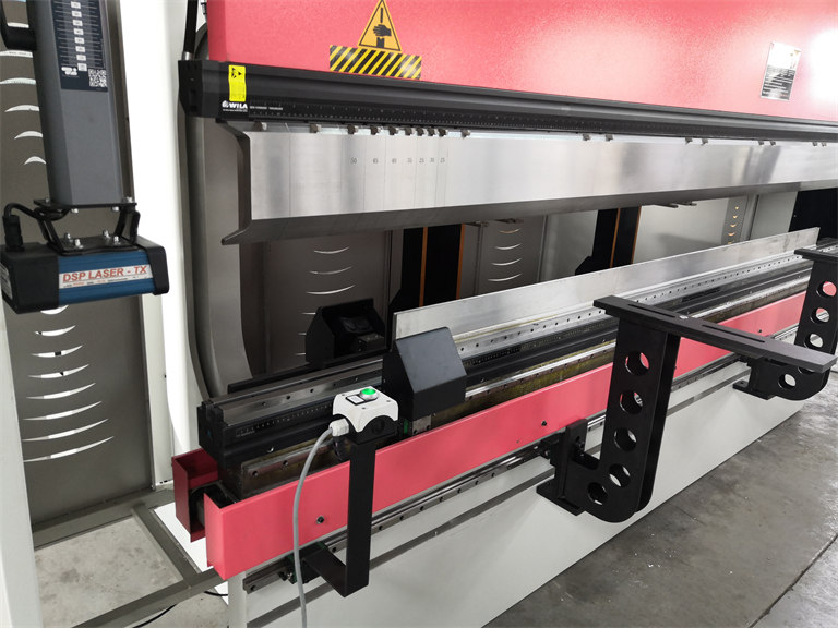
5. Bending Angle Laser Detection Device
The angle sensor of Bending Angle Laser Detection Device is controller with CNC Controller through corresponding software. It can take the first inspection to get the correct bending value, and save it in the CNC Controller system. When continuous batch bending, there is no need to repeat the test, just obtained the bending value of the workpiece directly. It can increase productivity and improve product quality
6. Bending Mould and Clamping
It is composed of two parts: upper bending punch and bottom die. The upper bending punch is installed on the sliding block and fixed by the splint. The bottom die can be various forms such as single V, double V and multiple V. The bending die can be divided into sections according to user requirements. A complete set of hydraulic clamping devices for the upper and lower molds are provided as standard, which is convenient for quick replacement of the upper mold.
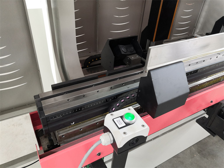
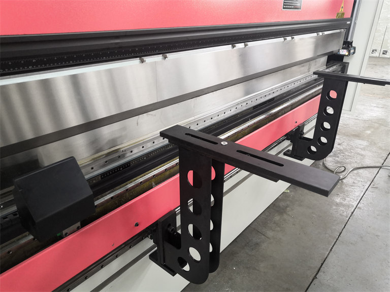
7.Front Support and Backgauge
Front Support:It is a standard part and is installed on the front of the working table. The front support bracket can be manually moved to an appropriate position according to the length of the workpiece, and the support bracket can be adjusted in the horizontal and vertical directions.
Backgauge: It is floor-standing independent backgauge structure. The structure of the backgauge system is processed by aluminum alloy profiles at one time. It has the characteristics of sturdiness and small inertia, so it has high speed, large load capacity and high accuracy. Unique modular design, the number of control axis can be selected from single X axis to multiple axis. This machine is equipped with X axis, R axis, Z1 axis and Z2 axis; with two standard K-type stops fingers.
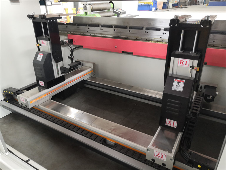
X axis is the overall front and back movement axis of the backgauge, which determines the size of the bending.
R axis is the overall up and down movement axis of the backgauge. The backgauge positioning speed is as fast as 400mm/s, which improves production efficiency greatly.
| Multi-axis | X axis | R axis | Z1, Z2 axis |
| Position Speed | 400mm/s | 400mm/s | 400mm/s |
| Re-positioning accuracy | ±0.025 mm | ±0.025 mm | ±0.025 mm |
| Positioning accuracy | ±0.025 mm | ±0.025 mm | ±0.025 mm |
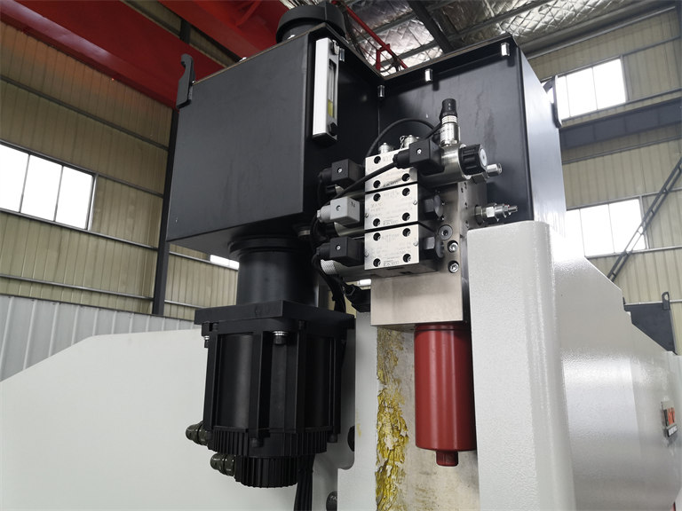
8. Hydraulic System:
The hydraulic system adopts an electro-hydraulic proportional servo control system to control the idle stroke, working stroke, return stroke of the piston rods of the two cylinders and the synchronous movement. The hydraulic system is equipped with an overload protection function.
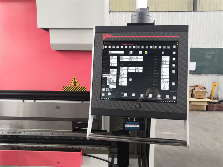
9. CNC Control System
The bending force is automatically calculated according to the thickness, material and length of plate, and the angle error correction amount is automatically calculated. It has a powerful bending expert data system and automatic programming functions.
 WhatsApp

 8613812394816
 Email
Email